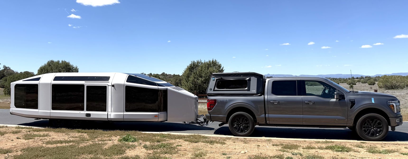

Crankshaft to bed outlet: how ProPower Onboard actually makes its power
The whole chain, in one picture
Every watt this project has ever delivered into the LightShip's 77 kWh pack while towing has taken the same path. It starts as crankshaft torque, becomes three-phase AC inside the bellhousing, is rectified to roughly 300 volts DC, sits briefly on a shared bus, is inverted back to 240 V AC by a second and entirely separate inverter, leaves through a twist-lock receptacle in the bed, and finally passes through the trailer's onboard charger into the cells.
Eight conversions. Each one takes its cut. That is why the measured yield is what it is, and why no clever operating strategy is going to move it much.
The modular hybrid transmission
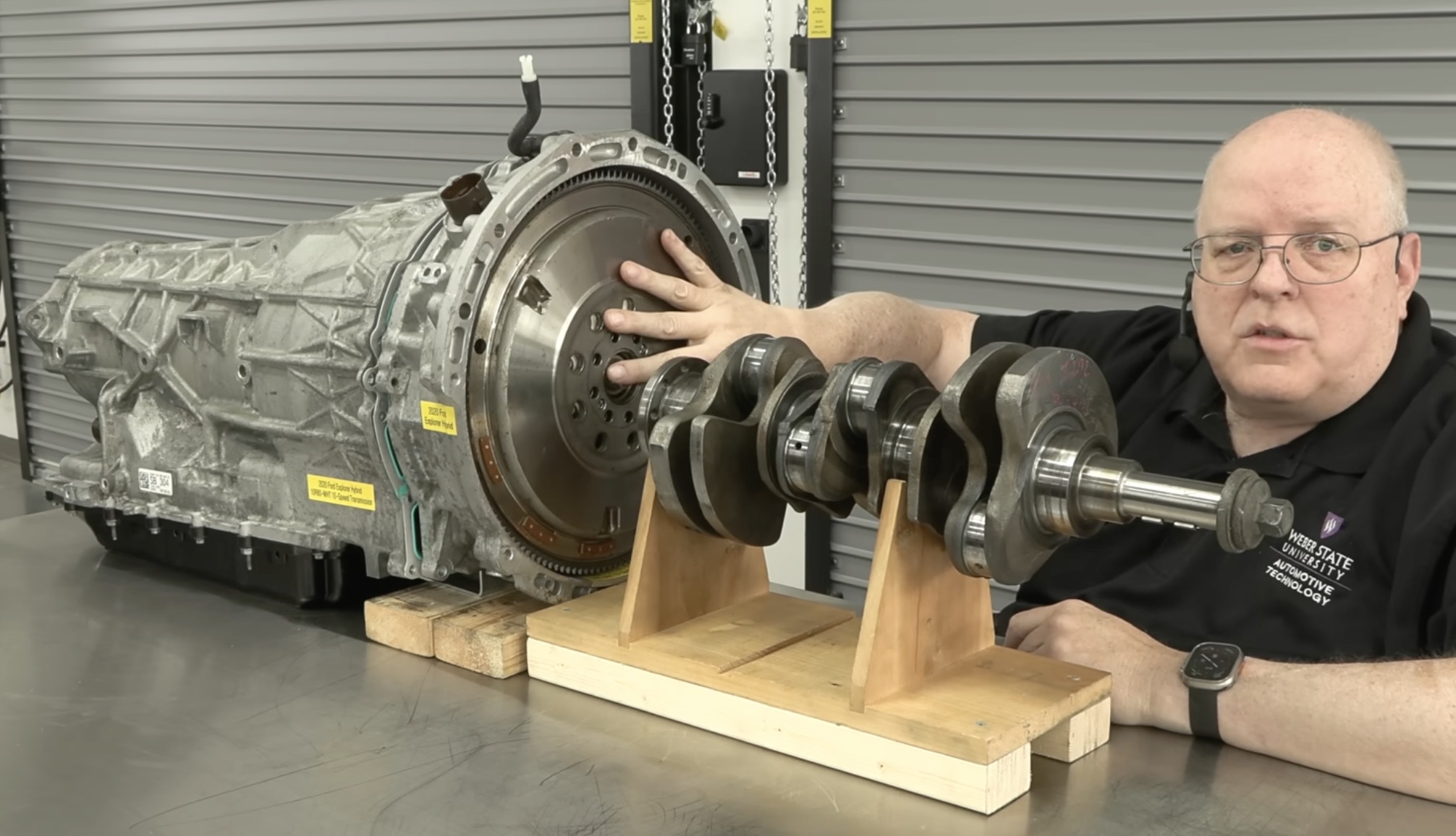
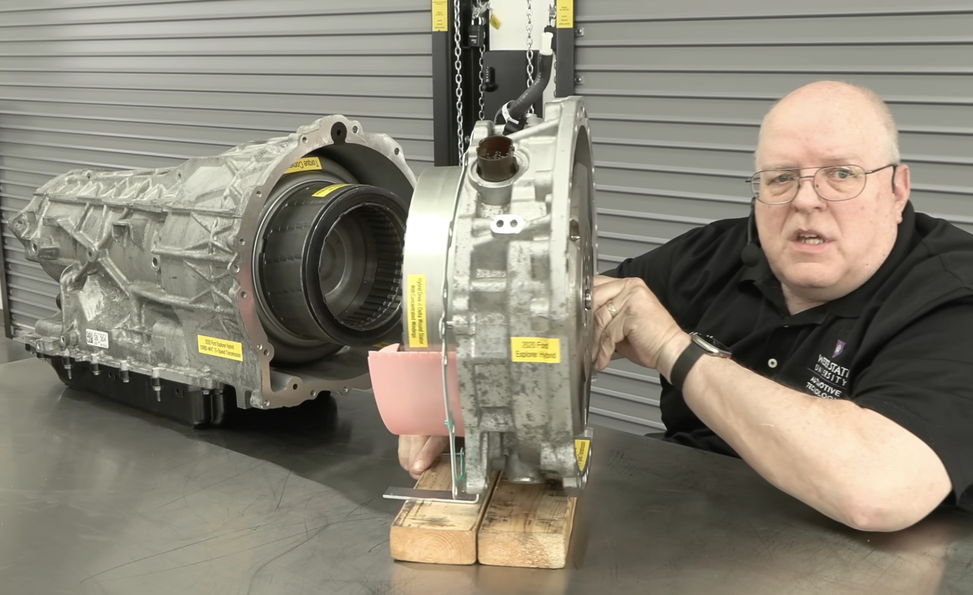
The F-150 PowerBoost uses a 10R80 ten-speed automatic with an extra module bolted to the front of the bellhousing. Ford calls the result the 10R80‑MHT — modular hybrid transmission. "Modular" is literal: the hybrid hardware is a bolt-on section forward of an otherwise conventional gearbox, and the transmission behind it shifts through all ten gears whether the power arriving is coming from the engine, the electric motor, or both.
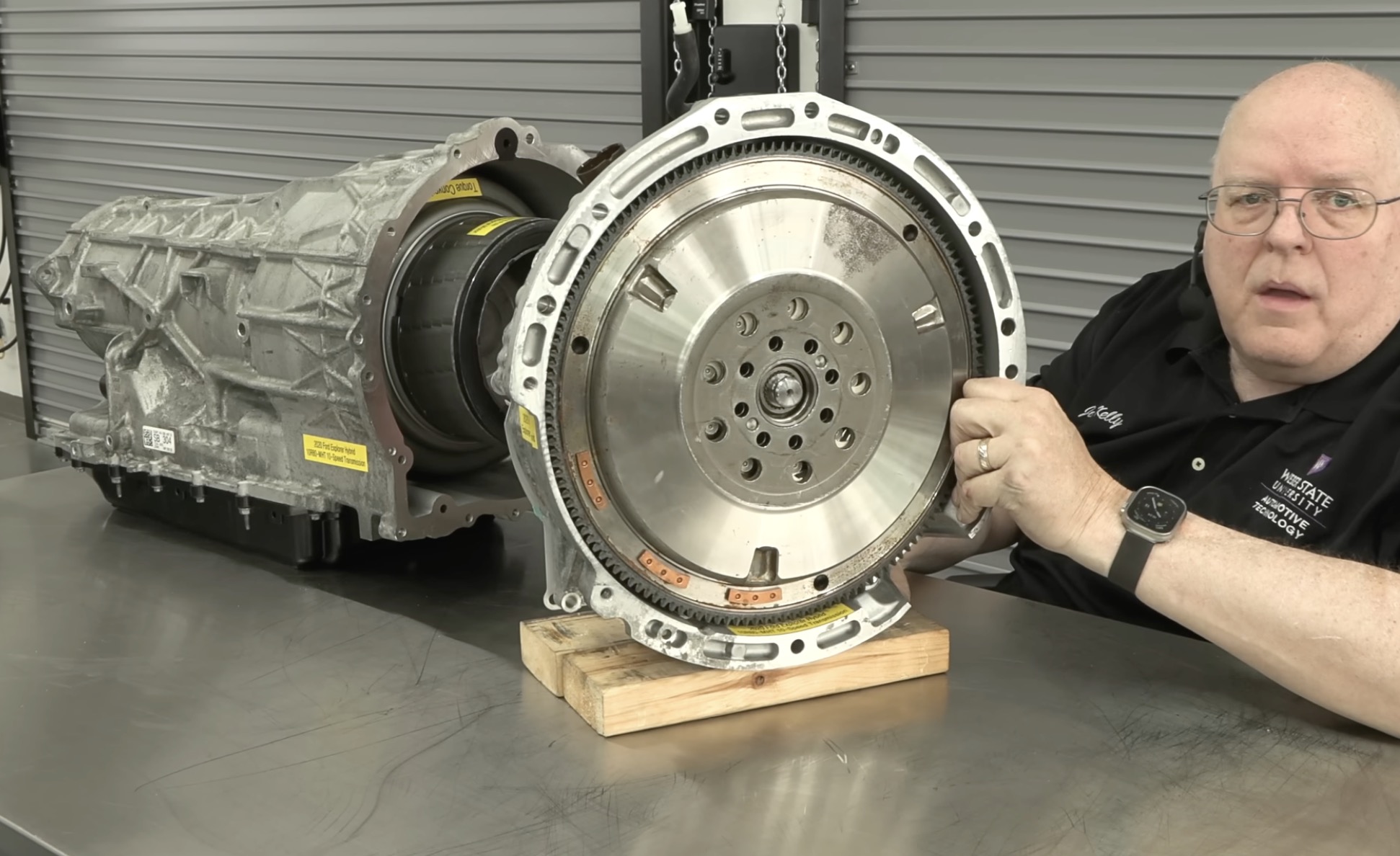
The architecture debuted on the 2020 Explorer Hybrid behind a 3.3 L V6. The F-150 PowerBoost is the same modular concept behind the 3.5 L twin-turbo. The teardown unit photographed below is the Explorer variant — same family, and the reason every dimension-specific claim on this page is drawn from the service manual rather than from the bench.
The machine that does all the work
Inside the module is a single electric machine: a 24-slot stator with concentrated delta windings, and an 8-pole internal-permanent-magnet rotor. The rotor is not on a shaft of its own — it is welded directly to the outside of the torque converter. That construction is the key to the whole system's behaviour. Rotor and torque converter are one rotating assembly, permanently coupled to the transmission input.
The label on the teardown unit puts the machine at 35 kW / 47 hp. Supplier is Schaeffler. No torque figure is published.
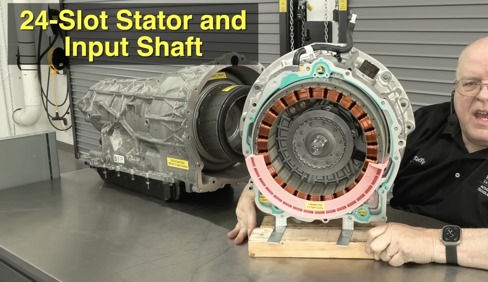
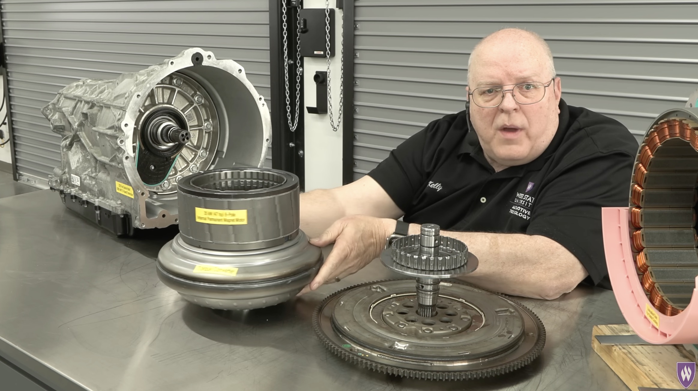
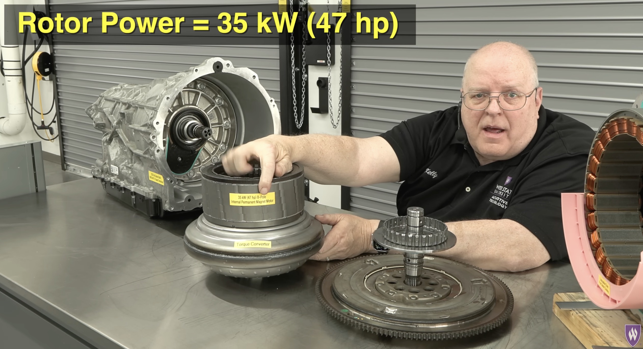
ProPower's 7.2 kW rating is 21% of this machine's 35 kW capacity. The 5.8 kW this project actually draws while towing is about 17%. That fraction is not spent from some separate accessory budget — it comes off the same rotor that would otherwise be assisting the engine or capturing regen. Section 09 works through what that means for TurboAssist.
The engine disconnect clutch
The input shaft from the flywheel does not drive the rotor directly. Left alone the two free-spin relative to each other. What joins them is a wet multi-disc clutch pack — three fibre discs and four steel plates, applied by a hydraulic piston fed through the bellhousing. The steel plates spline to the input shaft; the fibre discs spline to the rotor. Apply the pack and the engine is mechanically joined to the electric machine and to the transmission. Release it and the engine is gone.
This is what makes the F-150 PowerBoost a P2 hybrid: the electric machine sits between a disengageable engine and the transmission input. The belt-driven starter-generator on the front of the engine is a separate P0 machine, used for warm restarts.
The transmission carries an electric oil pump in addition to the engine-driven mechanical one, so hydraulic pressure survives engine-off operation. An extra solenoid on that electric pump is what applies the disconnect clutch.
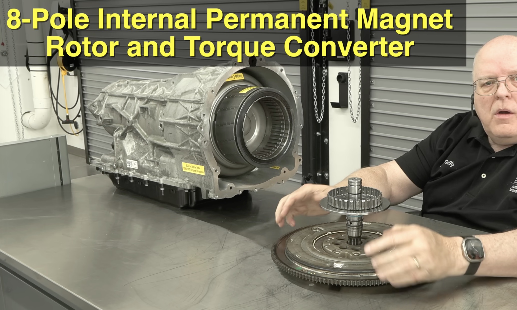
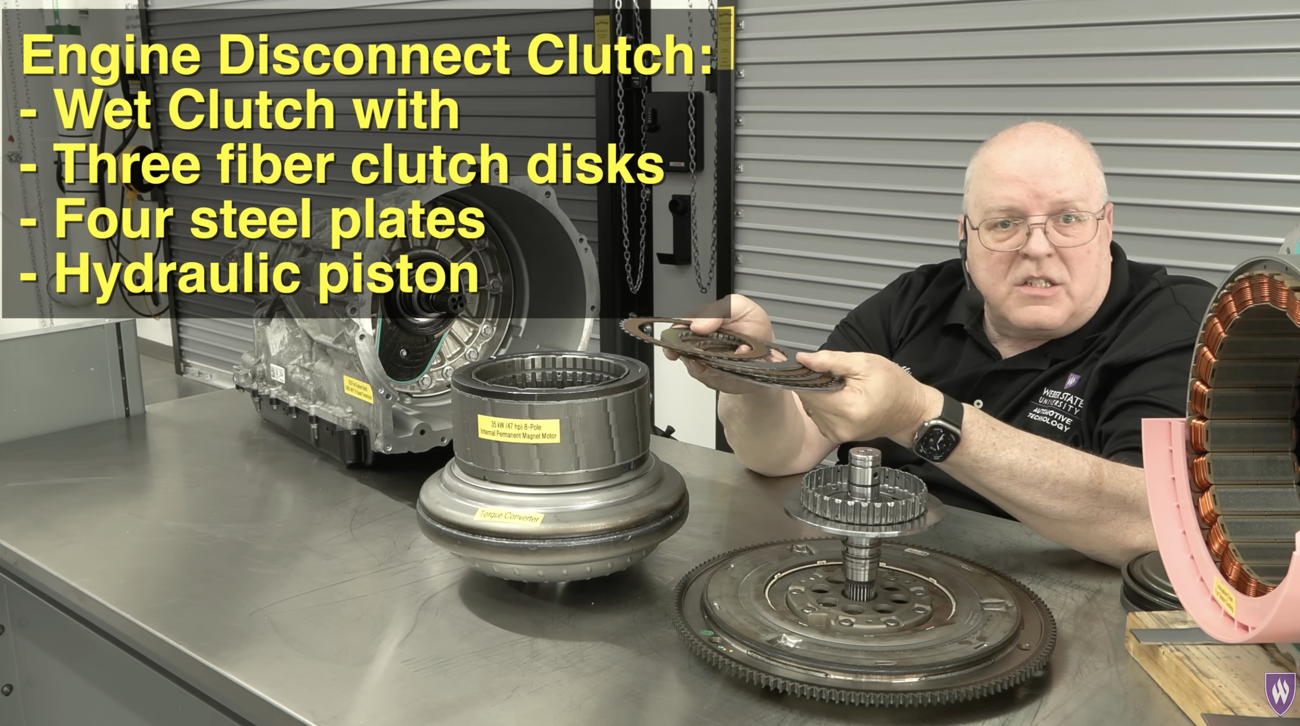
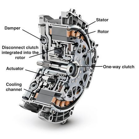
The obvious worry about a clutch that repeatedly reconnects a running engine is wear. The mitigation is that it is never asked to absorb much slip: the belt-driven starter-generator spins the engine up to match rotor speed first, and only then does the pack apply. Add a wet, ATF-lubricated design and the duty is mild. Field reports support this. It is still an operator-facing wear item worth knowing exists.
Four states, one of which pays for ProPower
The disconnect clutch gives the powertrain a small state machine. The factory service manual names four states; the structure is directly analogous to the State A / State B framing this project uses on the trailer side.
| State | Disconnect clutch | What happens | ProPower source |
|---|---|---|---|
| Electric drive | Disengaged | Engine off; motor alone drives the wheels | Pack only |
| Electric driven | Disengaged | Driveline inertia spins the motor as a generator — regen | Recovered energy |
| Hybrid drive | Engaged | Engine drives the wheels; torque above driver demand charges the pack through the motor; motor can also assist | Fuel |
| Engine start | Engaging | Motor torque splits between driveline and cranking | — |
Towing at highway speed, the truck lives almost entirely in hybrid drive. So the honest description of in-motion V2V charging is this: ProPower is a request for additional engine torque. The PCM meets a 5.8 kW electrical demand by asking the crankshaft for roughly 7 kW more mechanical power, and the fuel map does the rest.
The second row of that table is the interesting one. During regen the bus is being fed by recovered vehicle energy — routinely −10 to −14 kW on this rig, up to about −38 kW. A 5.8 kW ProPower draw taken during a descent is therefore partly or wholly not a fuel cost at all. Campaign 1 could not separate this: the 7.70 kWh/gal figure is a whole-campaign average that quietly includes whatever descent charging happened to occur.
It is computable, and has not yet been computed. The Campaign 2 stream (September 2026) carries DCACA high-voltage-side current, and the HV Battery Power channel was confirmed bus-terminal by the 2026-07-29 bench test. A descent-window energy balance — regen in, ProPower out, fuel rate throughout — would establish whether downhill charging is materially cheaper than the campaign average. As of this revision (6 September 2026) that reduction has not been run; the question stays open. What Campaign 2 did settle is the level-road cost: a commanded on/off step on flat I-10 at 62 mph priced 5.8 kW at 0.75 gal/hr (band 0.65–0.83), from the fuel channel alone. If descents come in materially below that, it is a route-planning finding with a real number behind it, and it belongs in the pitch.
One bus, five branches
Everything electrical on this truck converges on a single high-voltage bus at roughly 300 volts DC. The battery, the traction inverter, the DC/DC converter, the air-conditioning compressor and the ProPower inverter all connect to it through a BECM-controlled junction box with precharge sequencing and continuous isolation monitoring against the chassis.
Two details in that junction box matter more than they look.
- The fusing is deliberately asymmetric. A 150 A high-current fuse protects the traction side. A separate 50 A fuse protects the DCDC and DCACA together. A ProPower fault cannot propagate into traction — the topology structurally prevents it.
- ProPower and the 12 V system share that 50 A. At ~300 V that branch is good for roughly 15 kW. ProPower at full 7.2 kW output draws about 26 A from the bus; the 12 V system's draw was about 2 A on the bench and 0.62 kW mean (again about 2 A) over a 5.1-hour Campaign 2 leg in motion. Comfortable headroom, but they are on the same fuse, and any future accessory hung off the DCDC eats into ProPower's margin rather than traction's.
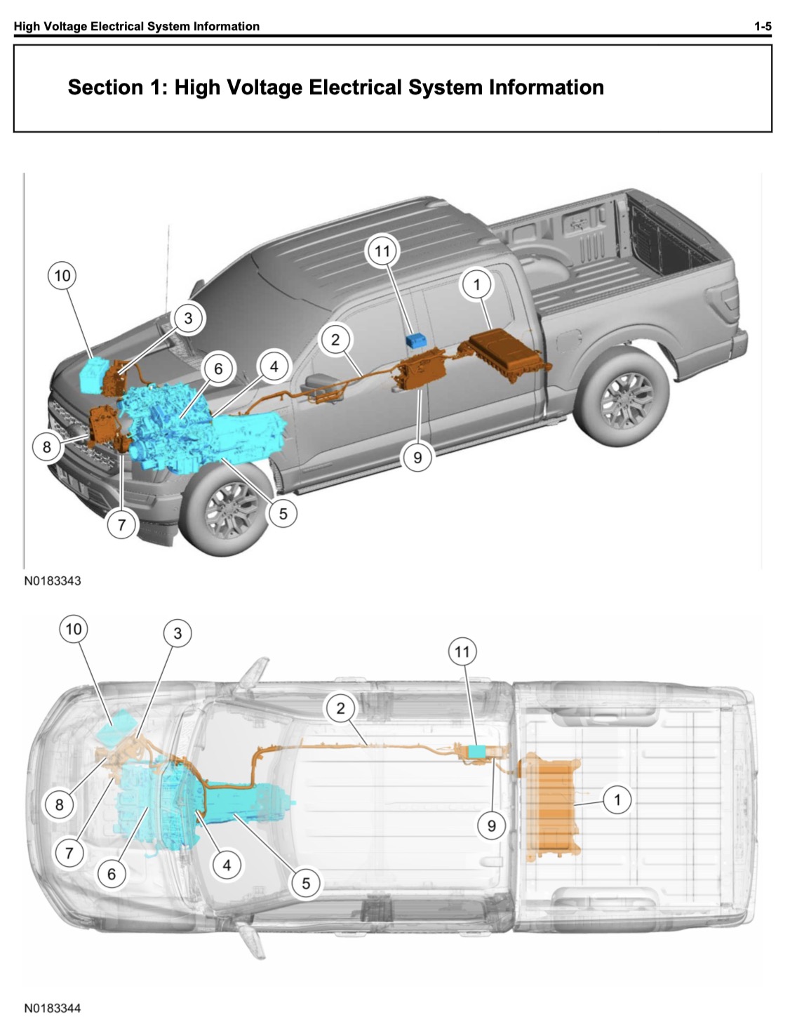
The callout list on the facing page is worth reading as a bus map rather than a parts list. Paraphrased, with this project's terminology in brackets:
| # | Component | Where it sits | What it does |
|---|---|---|---|
| 1 | High-voltage battery | Under the vehicle, aft | Liquid-cooled lithium-ion pack; the storage every other branch draws from |
| 2 | High-voltage cabling | Underbody, battery to engine bay | The bus itself. Orange sheathing throughout |
| 3 | Inverter System Controller (ISC/SOBDMC) | Under hood, passenger side | Traction inverter — DC to three-phase AC for the drive motor |
| 4 | Hybrid unit / HV electric motor | Between engine and transmission | Motor, torque converter and disconnect clutch in one housing [sections 02–04] |
| 5 | Transmission | Alongside the engine | 10-speed carrying the hybrid drive unit and its integral disconnect |
| 6 | Gasoline engine | Engine bay | 3.5 L; conventional in arrangement |
| 7 | Electric A/C compressor | Forward of the engine | High-voltage device with its own orange cable — replaces the belt-driven compressor [ACCM] |
| 8 | DC/DC converter | Under hood, passenger side, below the ISC | Steps the bus down to 12 V for the low-voltage battery and accessories [DCDC] |
| 9 | On-Board Generator Inverter (OBGI) | Under the vehicle, on the passenger frame rail ahead of the HV battery | Bus DC to AC for the ProPower Onboard bed and cab outlets [DCACA] |
| 10 | 12 V battery | Under hood, passenger side | Conventional negative-ground 12 V source |
| 11 | 12 V auxiliary battery | Under the right-hand rear seat | Carries transient loads through a crank event while the main battery is isolated |
Callout 7 confirms the compressor is a high-voltage device. It is described as electric with its own orange high-voltage cable, replacing the belt-driven unit — independent corroboration of this project's July correction, which had previously and wrongly described the compressor as a 12 V load hanging off the DC/DC converter. It draws from the bus directly, which is why it showed up in the bench test's HV Battery Power reading — and Campaign 2 metered it on its own channel (next readout).
Callout 9 locates the ProPower inverter. Ford's term here is On-Board Generator Inverter; the diagnostic literature this project works from calls the same module the DCACA. It is a physically separate unit from the traction inverter (callout 3) and sits in a different place entirely — underbody on the passenger frame rail, ahead of the pack, not under the hood. That is the architectural point section 07 makes, now visible in a drawing.
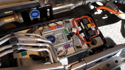
A long-standing open question about this bus was whether the scan-tool "HV Battery Power" channel reports total bus-terminal flow or only traction. A parked engine-off test settled it: against a quiet baseline of +0.80 kW, applying ~1.35 kW of ProPower load moved the channel to +2.09 kW, and adding the A/C compressor took it to +3.17 kW — with pack SOC falling 52.9% → 50.2% as the independent witness. The channel sees accessory load with no traction involvement. It is bus-terminal.
The +1.29 kW step against a 1.35 kW applied load establishes that the channel responds, not the converter's efficiency — the difference is inside the baseline uncertainty of the test.
The 46-PID, 1 Hz configuration of September 2026 added high-voltage-side current on the DC/DC converter and the ProPower inverter, and the compressor's own current channel. Moving-time means over the 5.1-hour Thermal → Prescott return: DC/DC 0.62 kW (3.17 kWh), A/C compressor 1.28 kW (6.52 kWh), accessory total without charging about 1.9 kW — the ~0.8 kW quiet engine-off baseline sits inside that figure. With the charger delivering, the ProPower inverter drew about 6.0 kW from the bus for 5.85 kW out, an inverter ratio of about 0.98 — the first direct measurement of that stage, and higher than the 0.94 this project had assumed.
The compressor also serves battery-chiller duty through a BECM-controlled diverter valve, so it cannot be fully switched off; its mean is a hot-day figure (93 °F ambient) and moves with the weather.
The pack is a buffer, not a reservoir. Ford publishes about 1.5 kWh; this project's multi-year field observation puts the working SOC band at roughly 40–62%, with a floor never seen below ~28% and a rare ceiling near 72%. Taking the full observed 28–62% span as usable gives on the order of 0.5 kWh — about five minutes at a 5.8 kW ProPower draw with the engine off. In practice the engine fires long before that.
The 1.5 kWh figure is a published product spec, not drawn from the service-manual extracts used elsewhere on this page; nominal capacity is not the same as usable. Treat the five minutes as an order-of-magnitude, not a number.
The DCACA: a second, separate inverter
ProPower Onboard is not a tap off the traction inverter. It is its own module — the DCACA — taking high-voltage DC off the bus and producing 120 V and 240 V AC. It has its own control logic, its own protection setpoints, and its own thermal limit, and it is cooled by the electric-powertrain coolant loop rather than by engine coolant.
| Protection | Threshold | Behaviour |
|---|---|---|
| HV input undervoltage | below 168 V DC | DTC sets; keeps trying to operate |
| HV input overvoltage | above 330 V DC | standby until the condition clears |
| 12 V supply | below 9 V / above 16 V | will not operate |
| Overload | >130% of rated for 2 s | shuts down |
| Over-temperature | 199.3 °F (93 °C) internal | standby until the condition clears; auto-recovers |
| CAN loss | no PCM message for 5 s | AC output disabled |
| Rated output | 7,200 W, 120/240 V combined | — |
| Keyed-on baseline | 400 W | available with Ready light on, no enable needed |
Three separate thermal domains exist on this vehicle and are easy to conflate. Engine coolant runs a 189.9–217.4 °F thermostat range. The electric-powertrain loop that cools the DCACA is capped far lower, at 158 °F. And the DCACA's own internal module temperature has that independent 199.3 °F cutoff, which is not the same measurement as either coolant loop.
Across every leg and every ambient condition of a 3,719-mile campaign, the DCACA delivered 5.69–6.06 kW whenever it was running — through 104 °F ambient — and Campaign 2 repeated the result at a 5.85 kW mean through 93 °F. Duty cycle varied enormously — battery-management cycling, deliberate operator reduction on hot climbs — but the rate never sagged. When this system runs, it runs at rate.
Campaign 1 produced exactly one confirmed temperature-driven charging stop, at the NACS receptacle on the Cortez → Durango leg, which resumed as ambient fell on the climb. The truck-side inverter's own cutoff sits 95–100 °F above where that dropout occurred, and the manual documents automatic recovery with no fixed lockout timer — yet charging did not resume for 30–45 minutes. The DCACA is therefore excluded with confidence; trailer-side EVSE, onboard-charger or battery-management logic remains the candidate. n = 1. The exclusion is sound. The lockout duration is not generalisable from one event, and this page does not pretend otherwise.
The bed panel, and the receptacle that sets the ceiling
The 7.2 kW configuration presents four 120 V / 20 A outlets in the bed plus one twist-lock NEMA L14-30R at 240 V / 30 A, with an additional 120 V outlet in the cab. The L14-30R is two 120 V legs of 30 A each; a 240 V load uses both.
That receptacle is where the NACS umbilical to the LightShip's AeroHub inlet begins, and it is also where an arithmetic constraint appears that is worth stating plainly.
240 V × 30 A = 7.2 kW. The truck's rated output and its bed receptacle's current limit are the same number — the inverter is rated exactly to what the plug can carry, with the overload trip sitting at 130% for two seconds above it. A Turbo Edition specified at 8 kW therefore could not be fed by ProPower Onboard alone on this truck: 8 kW at 240 V is 33.3 A, past the receptacle rating and past the inverter's continuous rating.
This is not necessarily a conflict — an 8 kW onboard-charger rating on the trailer may simply describe its shore-power or DC capability, with truck charging expected to run below it. But the distinction would need to be explicit in any future specification, and this project's own figures should keep saying what they are: prototype data taken at 5.8 kW, not validation of an 8 kW rating. The Turbo Edition is a concept in development, not a released product; nothing here describes a shipping specification.
The 5.8 kW this rig actually draws is set by the trailer's onboard charger, not by any truck-side limit. There is roughly 1.4 kW of unused headroom at the panel on every leg of every campaign so far.
What the chain costs
Eight conversions, each taking its cut. The measured result at the bed panel:
| Quantity | Value | Basis |
|---|---|---|
| AC energy per gallon, at the panel | 7.70 kWh/gal | measured, Campaign 1, seven independent legs over 3,719 mi (program reference; supersedes the June 557.6-mi round trip) |
| Fuel to generate 5.8 kW in motion | 0.75 gal/hr (band 0.65–0.83) | measured, Campaign 2 commanded on/off step, flat I-10 at 62 mph, 2026-09-05; 65 windows, R² 0.95; grade fitted, not assumed |
| AC per gallon, from the step test | 7.0–9.0 kWh/gal | measured band; matched-grade blocks 7.5. The Campaign 1 reference sits inside it |
| Delivering-state rate, Campaign 1 | 5.69–6.06 kW | measured, seven independent legs; no thermal derate through 104 °F |
| Delivering-state rate, Campaign 2 | 5.85 kW mean | measured; no derate through 93 °F |
| ProPower inverter, bus in → panel out | ~0.98 | measured, Campaign 2: ~6.0 kW HV-side for 5.85 kW AC |
| Fuel-economy cost of charging | ~1 mpg at 62–65 mph | 0.75 gal/hr on a ~4.5 gal/hr towing baseline |
| Crankshaft → AC at the panel | ~61–69% | modeled: crank side from the PCM torque model, which under-responds to load; indicative only |
| Fuel → AC at the panel | ~22.8% | modeled: 7.70 ÷ gasoline LHV (33.7 kWh/gal) |
| Fuel → energy in the cells | ~20.5–21% | modeled: above × ~92% onboard charger |
| Net charge rate into the pack | ~5.2–5.6 kW | modeled: measured AC output × ~92% |
| Cost per kWh into the cells | ~$0.49 | modeled at $3.50/gal and ~7.1 kWh/gal into the cells (~$0.45 at the panel) |
| Campaign 1 total delivered | 74.74 kWh AC | measured, bulk-charge basis, 3,719 mi |
| Charging's share of trip fuel | 3.8% (C1) · 5.9% (C2 return) | 9.71 of 258.59 gal; 9.69 kWh over 278 mi with charging on half the leg |
Two June-trip figures that stood in this table through revision 1.1 — a 5.36–5.80 kW “throttled” output band and a 0.697–0.753 gal/hr rate from a single 557.6-mile round trip — are withdrawn. The output band was contradicted by both campaigns (section 07); the fuel rate is replaced by the controlled step test, which is the measurement.
Through revision 1.1 this readout flagged two items on the V2V technical assessment: a 22.7% figure labelled full-chain "fuel LHV → LightShip cells" that is actually fuel-to-panel (the cells figure is ~20.5–21% after the onboard charger's ~92%), and a "theoretical 8.54 kWh/gal" that was the measurement divided by 0.902 rather than an independent prediction. Both were corrected in that page's revision 1.1 (6 September 2026): the label now reads at the panel, and the 8.54 is withdrawn. The record is kept here because the error propagated for three weeks before it was caught.
Why this matters to TurboAssist
Section 03 flagged the number to read twice, and this is where it lands. ProPower and electric traction assist are the same 35 kW machine. The machine cannot motor and generate simultaneously. So during exactly the events TurboAssist exists to address — a sustained high-load climb where engine thermal margin is disappearing — a running ProPower load must come from the pack, and the pack holds about five minutes. In practice the engine carries it.
That is a truck-side argument for moving assist onto the trailer's own axle motor, and it is one the current pitch does not make. The trailer's TrekDrive motor is a genuinely independent power source; the truck's is not. Campaign 1 measured the mechanical load transfer at 27.8% once the ProPower contribution is properly decomposed out — not the 47% a raw State A / State B comparison suggests, because the interlock means every TrekDrive-on run is also a ProPower-off run.
The competing-resource argument above follows from the architecture and from the 35 kW rating. It has not been instrumented. A clean test would be a matched pair of high-load climbs with ProPower on and off, watching whether the motor's contribution to traction changes. The Campaign 2 channel set carries the bus-side currents that test needs, but Campaign 2 did not run it, and one caveat now attaches: the truck's OBD engine-torque channel — the only truck-side force measurement — responds to load changes at about 80% of truth in the cruise regime, so a traction-split test would have to lean on the fuel channel and the bus currents rather than on brake torque. Until it is run, the argument is an inference, and it is labelled as one.
Kilowatts on sale at 70 mph
The previous section priced the chain. This one asks the question that number exists to answer: compared to what?
The honest comparison is not to a wall outlet. It is to the machine an RV owner would otherwise carry to make electricity from gasoline — a portable inverter generator, or a built-in RV genset. Against that field, the measured figure is not merely competitive.
| Source | kWh AC per gallon | Basis |
|---|---|---|
| ProPower, in motion, towing | 7.70 | measured, Campaign 1, seven legs over 3,719 mi; Campaign 2 step test brackets it at 7.0–9.0 |
| ProPower, parked, full 7.2 kW output | 6.55–7.20 | third-party instrumented + Ford estimate — not measured here |
| Four Honda EU2200i, paralleled to 7.2 kW | ~6.00 | published: 4 × 0.3 gal/hr at rated |
| Honda EU2200i at rated load (1,800 W) | ~6.06 | published: 0.95 gal tank, 3.2 hr at rated |
| Honda EU2000i at ~1.5 kW | ~4.76 | owner gravimetric fuel test, published |
| Honda EU2200i at 25% load (~550 W) | ~4.58 | published: 0.12 gal/hr at quarter load |
ProPower delivers roughly 27% more AC energy per gallon than a Honda EU2200i run at its rated load, and on the order of 60–70% more than the same class of generator run at the partial loads RV owners actually impose on them. The comparison figures are manufacturer-published or owner-measured; the 7.70 is this project's own instrumented result.
It is doing this while also moving 15,320 lb down the highway.
This is not a claim that the 3.5 L twin-turbo is a more thermally efficient engine than a Honda GXR120. It plainly is not, on any comparable basis. The advantage comes from somewhere else, and it is worth being precise about where, because the mechanism is also the limit.
The engine overhead is already paid. A generator's engine exists for one purpose. Every ounce of fuel it burns overcoming its own friction, pumping losses and warm-up is charged against its electrical output, because there is nothing else to charge it to. The PowerBoost's engine is running because you are towing a trailer at 62 mph. That fuel is already committed. ProPower is charged only the marginal fuel for the marginal load — and marginal efficiency at a good operating point is far better than average efficiency including start-up and idle.
The engine is already at a favourable operating point. Towing 15,320 lb at highway speed puts the 3.5 L at meaningful load, where brake-specific fuel consumption is near its best. Adding 5.8 kW — under 8 hp at the crankshaft — is a small increment on an engine already working in its efficient region. A small generator engine at rated load is at its best point too, but its best point is a much worse one: small displacement means proportionally higher friction and heat loss per unit of output.
The conversion chain is short. The motor-generator sits directly on the crankshaft through the disconnect clutch — no belt, no separate engine, no alternator rectification stage. Crankshaft to motor to bus to inverter to panel, and sections 02 through 08 walked every step of it.
Nothing is cold. The engine is at temperature, the catalyst is lit, the oil is thin. A generator started at a campsite pays all of that again every time.
The obvious objection is that this all collapses when the truck is parked. Stationary, the engine fires solely to make electricity; the overhead stops being sunk and gets charged back to the electrical output, exactly as it is for a generator. A large-displacement engine producing a few kilowatts ought to be operating deep in its inefficient region.
The published evidence says otherwise, and the reason is architectural.
An instrumented press test charged an electric vehicle from a parked PowerBoost for 2 hr 54 min, logging 30 A at 236 V average, then refuelled 3.133 gallons — 1.07 gal/hr. That works out to roughly 6.55 kWh AC per gallon. Ford's own estimate is about one gallon per hour at full output, which would put it nearer 7.2. Owner reports cluster in the same band.
So parked delivery runs 6.55–7.20 kWh/gal against 7.70 measured in motion — an in-motion premium of roughly 10–15% on the Campaign 1 reference, not the collapse the partial-load argument predicts. The Campaign 2 step test's 7.0–9.0 band overlaps the top of the parked range, so the premium is real but not large; the honest statement is that in motion is at least as cheap, and probably somewhat cheaper.
Why the penalty is small: the engine does not run at low load. It runs at a favourable load point and then shuts off, with the hybrid pack buffering the difference and the inverter drawing from the pack in between. Owners powering small household loads describe the engine starting every several minutes and running for a minute or two — not idling continuously at a fraction of capacity. The pack converts a variable electrical demand into intermittent operation at a good operating point, which is precisely what the partial-load penalty assumes cannot happen.
That is the same load-levelling behaviour section 05 described for the four drive states, doing useful work in a stationary application it was not obviously designed for.
An earlier draft of this section reasoned that a purpose-built generator sized to the load would probably beat a parked PowerBoost. The published figures do not support that, and the reasoning behind it — large engine, small load, poor efficiency — failed because it assumed continuous low-load operation the architecture does not use. The claim is withdrawn.
The parked figures above are third-party and published, not measured by this project. They are reported as such. Establishing a parked figure on this specific truck, with this project's own instrumentation, remains an open and straightforward bench measurement.
So the claim narrows rather than disappears: the kilowatts are cheapest while the truck is moving, because that is when the engine overhead is entirely sunk. But they are not expensive when it is parked. The discount is largest in motion and merely smaller at rest — which matters, because the stationary case is the one that covers the night the pedestal faults.
An electric tow vehicle exporting 240 V is moving stored energy, not making it — every kilowatt-hour sent to the trailer comes out of the traction pack that is also the rig's range. A conventional truck has a few hundred watts of accessory inverter, which is a laptop, not a charger. The parallel-hybrid architecture in sections 02 through 05 is what makes a tow vehicle capable of converting fuel into trailer kilowatts while under way, and at present it is close to alone in doing so at this scale.
What is documented, what is measured, what is open
- Documented. Bus topology, ~300 V nominal, asymmetric 150 A / 50 A fusing, precharge and isolation monitoring, the four-state drive machine, every DCACA protection setpoint, and the three thermal domains. All from the factory service manual, chapter-tagged for the 3.5 L PowerBoost.
- Third-party teardown. 35 kW / 47 hp rotor welded to the torque converter, 24-slot concentrated-winding stator, three-fibre / four-steel wet disconnect clutch, stator-specific ATF spray cooling (assembly-level ATF cooling is manual-confirmed; the stator path is the teardown's), electric oil pump holding pressure engine-off. Weber Auto bench unit is the Explorer variant of the same modular family.
- Measured here. 7.70 kWh AC per gallon at the panel (Campaign 1, seven legs), bracketed at 7.0–9.0 by the Campaign 2 step test. 0.75 gal/hr (0.65–0.83) to generate 5.8 kW at 62 mph on level ground — about 1 mpg. 5.69–6.06 kW delivering rate, 5.85 kW mean on Campaign 2, no derate observed at any ambient through 104 °F. Three distinct converter states, including a connected load-support state at 0.938–0.951 kW. HV Battery Power confirmed bus-terminal. DC/DC 0.62 kW and A/C compressor 1.28 kW moving means; ProPower inverter ratio ~0.98. 74.74 kWh delivered over Campaign 1 at 3.8% of campaign fuel; 5.9% on the Campaign 2 return.
- Open. Whether descent charging is materially cheaper than the level-road step-test cost (channels in hand since Campaign 2; not yet reduced). Whether ProPower measurably displaces traction assist under load (not run; the torque channel's ~80% load response limits how it can be run). A parked kWh/gal figure on this truck with this project's own instrumentation. Whether an 8 kW trailer-side charger rating and the truck's 7.2 kW receptacle limit would be reconciled in any future specification.
If you have questions or comments, please visit the LightShip RV Owners Club on RVForums.com and post them to this topic. I monitor that site regularly and would enjoy your feedback.
Mass basis measured — CAT scale + verified payload, 15,320 lb / 6,949 kg.
Factory sources: 2023 F-150 Hybrid Service Manual, sections 414-03A (HV battery and cables), 414-05 (voltage converter/inverter), 303-01G (electric motor), 303-06D (starting system / BISG), 302-03B and 303-03G (electric powertrain cooling).
Teardown source: Weber Auto (Prof. John Kelly, Weber State University Automotive Technology) — Ford modular hybrid transmission 10R80-MHT, “Ford's F-150 PowerBoost's One-Motor Hybrid System” ↗. Images 01–09 are frames from that presentation, used with credit; module cutaway is a supplier general-arrangement render. Descriptions are paraphrased throughout.
Product configuration (outlet count, NEMA L14-30R, ~1.5 kWh pack) from Ford published material and independent press coverage, not from the service-manual extracts.
Measured values green, modeled amber, flags rust, observations neutral — modeled numbers are never presented as measurements.
Campaign 2 figures (0.75 gal/hr step test, bus-branch means, inverter ratio, 5.85 kW mean) from the September 2026 leg reductions; reconciled to the Specifications page rev 1.2 on 2026-09-06.
System description · drafted 2026-08-07 · rev 1.2 brings Campaigns 1 and 2 current and withdraws the June-trip figures (section 09). The knowledge-base correction recorded in section 09 was resolved on the V2V page the same day; the specification question in section 08 stays open.